This part of my project isn't for the faint of heart. This isn't a tutorial. I skip a lot of stuff like reaction sun gears, low/reverse clutch packs, center supports, anti-clunk springs, bearings, shims, thrust washers, etc. If you aren't up for the risk of failure, maybe even, a thousand miles down the road, you may be better off to stay in bed and cough up the money for someone else to do this.
The first thing I learned when I rebuilt my TH 350 transmission is that you are far ahead to just buy a rebuilt one. It's like everything else in life, if you have done a hundred of these you can blow through it perfectly in a few hours. My rebuild took days. Partly because it was a learning process. Mostly because I'm very meticulous with this kind of thing, want to know how it works and why plus have everything perfect. I'm sure a pro doesn't stop to run feeler gauges in every clutch pack and assembly, run a micrometer on every bearing that he seats, etc. However the Pro job comes with a warranty.
So, here's a sampling of my process.
Here we are completely gutted. Everything is out including internals, externals and valve body. When I take things out I keep them all in order and separated by section, which is another thing I'm sure Pro's don't bother to do. For example, I want to be able to see if a torrington bearing has uneven wear and if the matching thrust washer has it too. Without keeping them in order, I don't know how I could do that. A Pro probably has a better process.
This is a bearing I took out. It has little to no wear and looks new. the clutches and steels looked new too. I'm positive this tranny was rebuilt just prior to being parked 12 or so years ago. I needed to rebuild it anyway because all the gaskets and seals were leaking like crazy from dry rot and I needed to have a stage 2 set of steels and clutches to handle the power the motor will put out...someday.
While I was pulling the spring pack out of the forward clutch, I took the opportunity to take a picture of my highly sophisticated & technical transmission work bench. Ok, its a 1" X 12" pine board with a 1 5/8" hole drilled in it set on half a whiskey barrel.
Without the specialized tools, replacing the bearings in the pump can be tricky. I made my own tool by bending the end of a hardened steel rod and then grinding a chisel point on it. It's long enough to go through the interior of the pump stator. I had to keep grinding a new chisel point on the rod and tweeking the bend, but as you can see, it worked. The other tools I got from Autozone on their loaner program.
Not having a pump alignment tool, I went to Lowe's and bought a couple of large hose clamps. They worked fine to clamp the two halves of the pump back together in perfect position while they are bolted. On the stator, you can see one silicone ring seal and the rest are old school steel. I had placed all silicone rings on there, but when I pressure tested the forward and direct clutch assemblies, they wouldn't seal. I was told that silicone rings don't pressure test well. However, I decided to replace them with steel so I would know 100% for sure, that the clutch packs operated normally.
Then I started at the end. With the rear piston, output shaft which you can't see because, it's going out the back into the whiskey barrel, and the rear planetary gear.
I put the forward clutch and the direct clutch assemblies together to make installation easier. Another thing that makes installation easier is to line up all the tabs on the clutches as like I have done in the photo of the direct clutch pack. That saves you a lot of time trying to jitter them around and work them done into their drive assembly.
The assembled direct and forward clutches are turned over and worked into their place..
In go the steels and clutchs for the intermediate / 2nd gear clutch pack. I'm using the stage 2 high energy clutches and steels that are rated for up to 550 HP.
Lastly the valve body. this is where I had most of my issues. I decided to install a Transgo shift kit for a little harder shift and the ability to adjust a few things in the shifting if I decide I want to. Installing the kit basically amounts to swapping some springs in the valve body and governor. It all went pretty easy until one of the new springs (similar to the one furthest to the left in the picture) slipped out of my grip, binged off the wall in front of me and disappeared. I spent the next 2 hours crawling around my garage and looking in every nook and cranny for that tiny spring. I finally found it down in a pencil holder on my work bench. The next major issue which isn't shown in these pictures happened when a small "S" hook that connects the manual shift valve on the opposite side of this valve assembley, slipped off and fell down into the transmission. I had to take everything out, back to the rear piston to get to it, and then re-install it all. All told, I really rebuilt this transmission two or three times with the issues I had.
Here are those stinking little springs in their new home.
With the governor installed,
The separator plate installed (you can see that nasty little "S" hook on the right),
All the valves back in and the valve assembly installed,
The speedometer back in and all the covers on,
I slapped some paint on the old girl and swore to never do it again...until the next time.
Tuesday, June 23, 2015
Monday, June 22, 2015
Brake lines
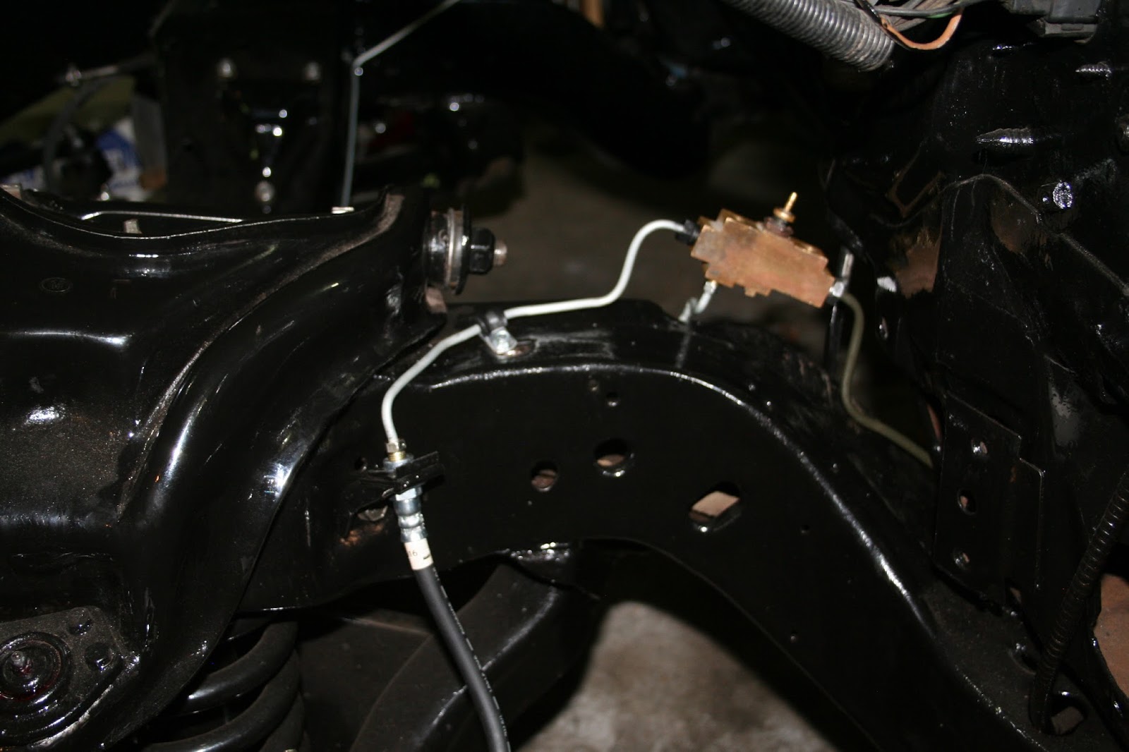
The transmission was getting on my nerves a little. My number one rule with this project is that when it stops being fun, I stop working on it. There have been a few glitches with the transmission. More on that, in the next installment. So, I let it set for a little while and switched to working on the brake lines. They had to be finished before the engine goes back in anyway.
A large portion of the brake lines had to be re-routed because of the headers. We had access to a shop with a lift and took off the stock exhaust and put on a set of headers and dual pipes about a year and a half ago. I'm glad we did. It brought to light a couple of problems that needed to be addressed.
The new home is above the frame. I have a staging lock to put on, but that won't be going on until the master cylinder goes on, which won't be until after the engine is back.
Monday, April 27, 2015
Engine Paint
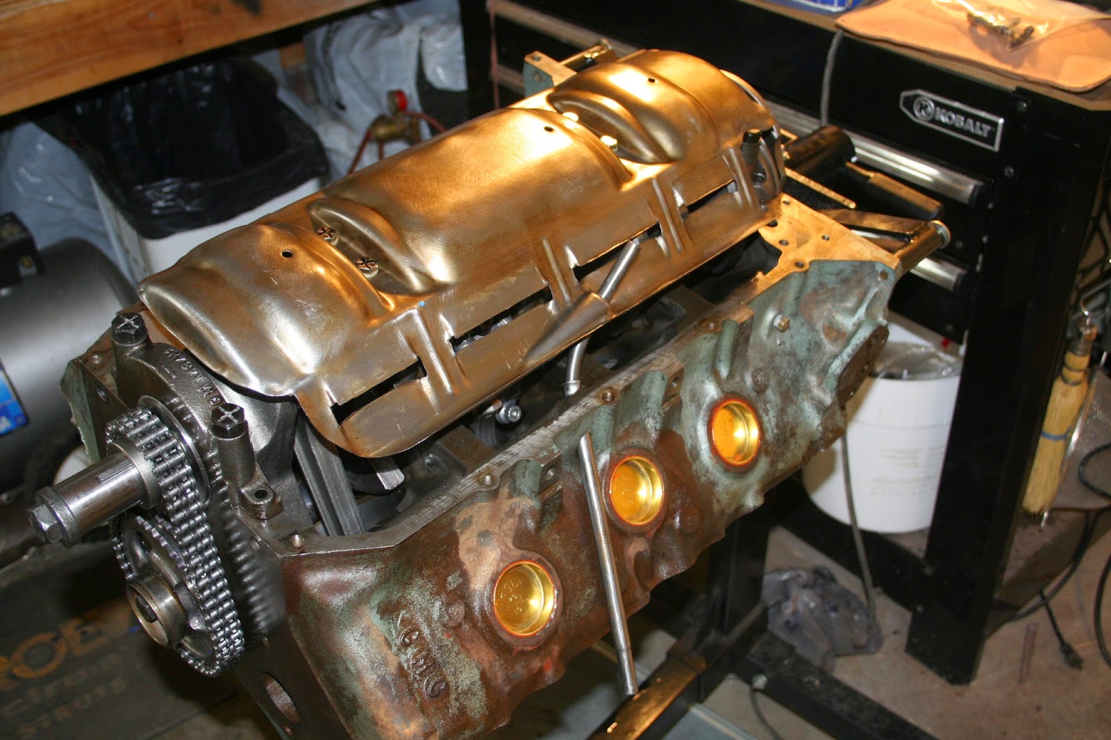
With the engine all buttoned up, it was time for paint. I used "Motor Coater" in the Metallic Pontiac Blue that was used during the years my engine was produced. You can apply most of these kinds of paint with a brush. I did that with the POR-15 I used earlier and it came out really nice. However, since this was a metallic, it would have streaked on anything that wasn't cast iron, so I shot it with a spray gun. All I had was my little 3.5 HP compressor with a 10 gallon tank. I could shoot about one side of the engine before running out of air. If you tried to paint a car with an HVLP gun and a small compressor like that, you would burn up the compressor before you finished the side of the car.
The engine was cleaned to the point of not having loose debris when it came back from the machinist. The heads were really clean because he did quite a bit of work on those with new valve seats and things.
The Motor Coater system is just like the POR-15 paint system. There is a degreaser that's used first. That part of the process took forever. I did a lot of soaking and a lot of work with a wire wheel to get it to the point where a cloth wiped clean and then it got some flash rust about as soon as it dried from the rinse.
After that comes the "Rust Blaster". It's a phosphoric acid solution that converts the rust (iron oxide) into a zinc phosphate that is bound to the metal and to which paint can bind. You don't have to get all the rust off and it's even advisable to have a little still on there instead of bare, shiny, clean metal. You just can't have any loose rust.
Here's a before and after. Some day I'll dress it up a little with some chrome valve covers and stuff, but for now, I'm more interested in getting it on the road than looking pretty on an engine stand.
For now, I've painted the stock intake to save some money. I plan to upgrade it later.
Friday, April 24, 2015
Closing up the engine
I got a lot of work done on the engine the last week or so.
The timing chain went on next with the timing marks both at 12 o'clock
and the #1 piston at TDC. Then the fuel pump concentric went on. This
is what holds the cam shaft in it's proper place. I was confused about
it being able to freewheel earlier.
I turned the engine over and installed the windage tray. Pontiac installed these in the high performance engines for a few years. They reduce the foam in the oil so the oil pump can pump a solid flow of liquid. I didn't even have to rotate the crank to know I had a problem. The enlarged counter balances on the Stroker Crank were touching the tray as soon as I put it on. I fabricated some spacers that dropped the tray about 1/4" to give me the clearance I needed. Then, everything rotated fine.
I'm slightly OCD and worry about and triple check everything. I put the oil pump in a container of break-in oil and ran it just to make sure everything was operational. Oil pump installation was a little touchy trying to get the bolts, gasket and drive shaft all lined up and in place all at the same time...and I failed. After installation, as is my OCD tendancy, I rotated the crank and, CLUNK. It was stuck. A little investigation told me that the drive shaft for the pump had somehow slipped out and got away. The crank shaft had caught on it. The bad news is I had to redo it all. The good news is, I found it now instead of when the motor is in the car!
Not wanting to leave anything to chance, I did make one minor mod on the oil pump. After inserting the pickup tube into the pump assembly, I made a small tack weld to insure it stays there. It's not a pretty weld, but I was mostly concerned about burning through the pick up tube not making it pretty.
Then the timing chain cover went on. In a previous post, I showed how I had cleaned this in my wife's dishwasher after I had done all I could with solvent. That worked great and got all the grease out of the minute scratches. It came out looking new. Just sitting for a couple of months, the inside became discolored. Antifreeze is some nasty stuff.
I refurbished the old oil pan and reused it. It's not pretty, but on my car it won't be seen at least in the near future and I need to put my money where it will make a difference. So, I just beat the dents out of this one, made sure it was flush and put it back on. I'm not impressed with Pontiac's oil pan gasket design. That 4 piece gasket gives a lot of opportunities for leaks.
Before permanently affixing the heads, I put some modeling clay on a couple of piston heads then, put on the head gasket, lightly secured the head with old bolts, and rotated the crank. As you can see in this after photo, I have plenty of valve clearance. The valves didn't even put a mark in the clay.
After checking the valve clearance and cleaning everything up, I installed the heads with ARP head studs. My mechanic son was questioning why some studs didn't seem to be in all the way. I had the same question when I installed them and it's the way the engine was bored and tapped I guess because the holes weren't all a uniform depth. Yes, there were some studs that were longer than others and I got them all in the correct placement or they wouldn't have fit at all. I'm not too worried about it because none of them were seated shallow or anything like that.
Finally! A new high flow water pump with new internal dividers because the old ones were rusted through. Everything's masked ready to start cleaning, prepping and painting.
The first piston in
All the pistons went in without a hitch. I checked gaps and clearances. Everything seemed good. I rotated the crank after each piston and at each stage after this. Everything was smooth as silk.
I turned the engine over and installed the windage tray. Pontiac installed these in the high performance engines for a few years. They reduce the foam in the oil so the oil pump can pump a solid flow of liquid. I didn't even have to rotate the crank to know I had a problem. The enlarged counter balances on the Stroker Crank were touching the tray as soon as I put it on. I fabricated some spacers that dropped the tray about 1/4" to give me the clearance I needed. Then, everything rotated fine.
I'm slightly OCD and worry about and triple check everything. I put the oil pump in a container of break-in oil and ran it just to make sure everything was operational. Oil pump installation was a little touchy trying to get the bolts, gasket and drive shaft all lined up and in place all at the same time...and I failed. After installation, as is my OCD tendancy, I rotated the crank and, CLUNK. It was stuck. A little investigation told me that the drive shaft for the pump had somehow slipped out and got away. The crank shaft had caught on it. The bad news is I had to redo it all. The good news is, I found it now instead of when the motor is in the car!
Not wanting to leave anything to chance, I did make one minor mod on the oil pump. After inserting the pickup tube into the pump assembly, I made a small tack weld to insure it stays there. It's not a pretty weld, but I was mostly concerned about burning through the pick up tube not making it pretty.
Then the timing chain cover went on. In a previous post, I showed how I had cleaned this in my wife's dishwasher after I had done all I could with solvent. That worked great and got all the grease out of the minute scratches. It came out looking new. Just sitting for a couple of months, the inside became discolored. Antifreeze is some nasty stuff.
I refurbished the old oil pan and reused it. It's not pretty, but on my car it won't be seen at least in the near future and I need to put my money where it will make a difference. So, I just beat the dents out of this one, made sure it was flush and put it back on. I'm not impressed with Pontiac's oil pan gasket design. That 4 piece gasket gives a lot of opportunities for leaks.
Before permanently affixing the heads, I put some modeling clay on a couple of piston heads then, put on the head gasket, lightly secured the head with old bolts, and rotated the crank. As you can see in this after photo, I have plenty of valve clearance. The valves didn't even put a mark in the clay.
After checking the valve clearance and cleaning everything up, I installed the heads with ARP head studs. My mechanic son was questioning why some studs didn't seem to be in all the way. I had the same question when I installed them and it's the way the engine was bored and tapped I guess because the holes weren't all a uniform depth. Yes, there were some studs that were longer than others and I got them all in the correct placement or they wouldn't have fit at all. I'm not too worried about it because none of them were seated shallow or anything like that.
Finally! A new high flow water pump with new internal dividers because the old ones were rusted through. Everything's masked ready to start cleaning, prepping and painting.
It doesn't even look like the same engine.
Thursday, April 16, 2015
Cam & Crank
It's finally time to start putting in something that moves. I had the machinist install the cam bearings. I paid him less to do it than I would have spent on the tool I would need to do it myself.
I went with the Summit Racing 2802 cam. I've read a lot of reviews that talk about it being pretty wild in a 350, a little lumpy in a 400 and maybe not big enough in a 455. Since mine is bored and stroked to a 461, I felt pretty comfortable putting it in. I also talked to a couple of people who have it and they like it. In the picture above, you can't really see much difference from the stock cam on the left. I measured it and there's a few thousandths difference in height from center, but the big difference seems to be in the pinnacle of the lobe which is wider and will give a little more duration for an open valve.
So, in it went. No problems as I carefully put it in through the bearings and continually lubed it with Royal Purple Assembly lube on the bearings. Then I coated the lobes with the break in lube provided by the manufacturer. I know a lot of people put the crankshaft in first. I preferred cam first, because it gave me so much more room to fiddle with the cam from the bottom of the engine without the crankshaft in place.
I was a little worried / concerned about how the cam would stay lined up with the lifters. As far as I could see, there would be nothing to keep it from sliding back against the block or forward against the cam retainer shown here. When I put on the timing chain later, it became clear how it's all held together.
Next came the crankshaft. I used plastigage on each bearing. They were all very consistent at about .0017 (a little more than the .002 mark but not as wide as .0015) which was right in the middle of my range. So, in went the crank.
Now, things will start to progress a little faster. I'm using Royal Purple's assembly lube. I had a lot of good reports about it and so far, I really like it. It has the consistency of honey and it's a little difficult to actually get off stuff where you may not want it unless you use brake cleaner or something. I guess the real test will be when I finally turn the key.
Old cam on the left new cam on the right
So, in it went. No problems as I carefully put it in through the bearings and continually lubed it with Royal Purple Assembly lube on the bearings. Then I coated the lobes with the break in lube provided by the manufacturer. I know a lot of people put the crankshaft in first. I preferred cam first, because it gave me so much more room to fiddle with the cam from the bottom of the engine without the crankshaft in place.
I was a little worried / concerned about how the cam would stay lined up with the lifters. As far as I could see, there would be nothing to keep it from sliding back against the block or forward against the cam retainer shown here. When I put on the timing chain later, it became clear how it's all held together.
Next came the crankshaft. I used plastigage on each bearing. They were all very consistent at about .0017 (a little more than the .002 mark but not as wide as .0015) which was right in the middle of my range. So, in went the crank.
Now, things will start to progress a little faster. I'm using Royal Purple's assembly lube. I had a lot of good reports about it and so far, I really like it. It has the consistency of honey and it's a little difficult to actually get off stuff where you may not want it unless you use brake cleaner or something. I guess the real test will be when I finally turn the key.
Tuesday, March 3, 2015
Pre-assembly
The long awaited return of my block and heads from the machine shop finally arrived. My machinist has been in the business for over 30 years. He only takes projects from people he knows. I had to have a reference from a friend of a friend. He had my engine for almost a year. I finally got to the front of the line and it was worth it. This guy is old school good. Very meticulous with a lot of attention to detail. For example, he wouldn't just bore and hone to spec. He had to have pistons in hand. And even though the crank came balanced and my flywheel and harmonic damper were already balanced, he said they haven't been balanced together and made some minor adjustments.
So I put the freeze plugs in along with the oil galley plugs. Yes, even the hidden one. I considered drilling a hole in the hidden oil plug to spray oil on the distributor and gear, but decided against it. I thought if Pontiac engineers thought it was good, then I didn't want to reduce oil pressure to other systems. It will be much easier to replace a distributor that didn't get enough oil than it would be to replace a crank.
Now there's a thing of beauty! A freshly machined head with those big Pontiac valves. Another thing the machinist did was to put steel seats under the valves. He told me that today's fuels would corrode the lip of the iron around the valve and eventually it would start to leak. So, he put in steel seats to maintain compression for years to come, at least through my life time.
The next step was to calculate compression. To do that, I needed the volume of the heads. A piece of plastic, a syringe, insert a spark plug and fill with water. These turned out to be 30 cc heads, which is what I guessed. I measured a couple of combustion chambers to be sure. After running the calculations, I came up with a compression ratio of 11.2:1 Looks like I'll be running Premium.
After practicing on some of the old rings, I finally developed a process where I could grind them perfectly square. There are a lot of YouTube videos and things where people say to only grind one side so you have a factory side that is perfectly square. I just could not grind one side and keep the ring in a position that would make the grind perfect.
After a lot of trial and error on old rings, and a lot of measuring, I found that if I pushed both ends of the ring into the wheels on my grinder and lined up the side closest to me so that it was barely touching the edge of the crank retaining pin hole, I could get a perfectly square and flat grind every time.
The rings were gapped for a 200 HP shot of Nitrous. I probably won't run spray to begin with and when I install it, I won't use it all the time. I called Mahle and the tech guy told me that on my setup, I wouldn't notice any "blow by" when I'm not shooting the juice, with the extra couple of thousandths I had to take off the rings.
I am very confident with my ring filing. Through this engine building process, I've learned that I have some very minor OCD issues. I always end up measuring things like the ring gap half a dozen times...on each ring. File, check, file, check, file check, check, check, check, ya it took forever. But they are perfect. I used an old piston to position them in the cylinder squarely for the measurement.
I filed each ring to fit a specific cylinder, not that it would have made a lot of difference, but I felt better and then I would move to the next cylinder.
When I finished, I just left all the rings waiting in their respective cylinders so I didn't have to put them on a peg board or worry about getting them mixed up
The pistons were then assembled, valve notches up and crank chamfers out. With the wrist pins drenched in assembly lube. The wrist pins were a "clip in type" instead of a "press in type", lucky for me. I decided to use the Royal Purple assembly lube. I read a lot of good about it, got a bottle and it's super slick yet sticky. When I took this engine apart I found gobs of assembly lube paste in the oil pan and corners of the valve cover area on the heads. I didn't want that. So far, I really like the Royal Purple stuff. We'll see how well it works at startup.
Subscribe to:
Posts (Atom)